For replacing a physical remote access VPN implementation with a VPN server in a virtual machine, one of the options is SoftEther. There is a lot of documentation in the site but somehow I felt the material was hard to absorb. In this post I describe the reference implementation I managed to complete with SoftEther.
Here is the network-level implementation I was attempting to do:
 The VPN server has a public IP address in the DMZ segment (198.51.100.9) and it is also connected to the VPN link network with a private IP address (10.1.1.4). The inside segment is just a /28 link network as the /24 VPN pool (10.1.32.0/24) is a routed network “inside” the VPN server. This is pretty normal type of VPN implementation. The VPN user’s traffic to the inside networks thus flows through the VPN link network.
I couldn’t find this kind of implementation in the documentation (or I just missed some details, let me know if that happened) so here are my notes about it.
First off, in SoftEther there are concepts like local bridge, Virtual Hub, Virtual L3 Switch, Virtual NAT and Virtual DHCP Server. Here are the short explanations for the networking-minded people:
- Virtual Hub is an internal virtual switch inside the SoftEther software. Something is logically connected to it. That “something” can be at least a VPN user (when logged in to the VPN) or a Virtual L3 Switch, or a NIC of the server when the local bridge is used.
- Local bridge is the possibility to connect a Virtual Hub to the network interface of the server, whether a virtual NIC or physical NIC, depending on the type of server. It is not mandatory to bridge all of the Virtual Hubs to NICs. Below I will show you my implementation where only one of the two Virtual Hubs are bridged to a NIC.
- Virtual Layer 3 Switch can be used to route traffic between Virtual Hubs. It is not needed in all implementations but here it will be needed.
- Virtual NAT can be used if you want to hide the VPN client traffic behind just one IP address. In my mind Virtual NAT is only useful if you only have one inside IP address for your VPN server, like when nobody actually knows you are running a VPN server. Otherwise you usually want each VPN client to have an own IP address, assigned from the VPN pool. Virtual NAT is a part of SecureNAT feature in SoftEther. I’m not using NAT in this implementation.
- Virtual DHCP Server is also a part of SecureNAT. It can be used if you want to give IP addresses to the clients automatically from the VPN pool, and in my case it is used.
The simpliest SoftEther remote access VPN configurations consist of only one Virtual Hub that is locally bridged to the NIC of the server. It means that the remote user connects to the IP address of the server, and after successful login the user’s traffic will be bridged to the NIC of the server. However, in this configuration the VPN client IP addresses can only be allocated from the network segment that the NIC is connected to.
In my case I wanted to have a routed pool of IP addresses to be used for the VPN users, so I needed something else.
Here is the logical representation of the implementation I made:
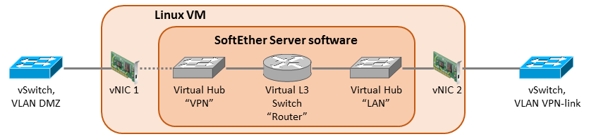 The VM (Debian Linux server) has two vNICs configured: one for the DMZ VLAN and one for the inside VPN link VLAN. The outside NIC has the public IP address (198.51.100.9) configured in the OS. The inside NIC has the private IP address 10.1.1.4 from the VPN link network.
The VPN Server Installation
I’ll just skip the actual VPN Server software installation steps here. Please study the installation guide in SoftEther.org. Then install the SoftEther VPN Server Manager for Windows and connect the VPN server with it to do the further configurations in GUI.
The Virtual Hubs
In SoftEther I created two Virtual Hubs:
- The first Virtual Hub is called “LAN“. It is locally bridged to the vNIC 2, called eth1 in my Debian. The configuration path is: Local Bridge Settings – Select the Virtual Hub to Bridge = “LAN”, LAN Adapter = eth1 – Create Local Bridge.
- The second Virtual Hub is called “VPN“. It is the hub where the VPN users connect. It needs to have specific settings in my scenario:
- Users need to be created. You can use local authentication or RADIUS. More about RADIUS details later in this post.
- SecureNAT needs to be enabled, not for the NAT functionality but for the DHCP server. In SecureNAT configuration here is what is needed:
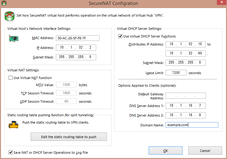
- In the SecureNAT configuration it is also necessary to add static routes for the inside networks if split tunneling is to be implemented. In this case the correct static route statement behind the “Edit the static routing table to push” button is: 10.1.0.0/255.255.0.0/10.1.32.1. Again, this is the route that will be pushed to the VPN users’ computers so that the correct traffic can be tunneled to VPN.
- The VPN hub is not “locally bridged” to any of the NICs. That’s why I have the dotted line in the diagram above. The bridging is not needed because the incoming users will be mapped to the VPN hub in the L2TP configuration.
The Virtual Layer 3 Switch
Ok, now we have the two Virtual Hubs but we need to get them talking to each other somehow. So there comes the Virtual Layer 3 Switch. I create one with name “Router“, and then I create two Virtual Interfaces for it:
- Virtual Hub = VPN; IP address = 10.1.32.1; Subnet Mask = 255.255.255.0
- Virtual Hub = LAN; IP address = 10.1.1.5; Subnet Mask = 255.255.255.240
The VPN hub interface (10.1.32.1) will be the gateway address for the VPN users’ tunneled routes. It was used as the gateway for the pushed route in the SecureNAT configuration above. The LAN hub interface IP address 10.1.1.5 is not the IP address of the Debian server! This is the address where the VPN pool (10.1.32.0/24) will be routed in the firewall.
Additionally, I configure the default route in Router, pointing to the inside network:
- Network Address = 0.0.0.0; Subnet Mask = 0.0.0.0; Gateway Address = 10.1.1.1; Metric Value = 1
This route is only used for the traffic that comes from the VPN users to the VPN server. It is also possible to just add the 10.1.0.0/16 route instead of the default route if you don’t plan allowing tunneled Internet access for the VPN users. Just add all the inside routes instead of the default route.
Note that the Debian server’s default route still points to the public Internet.
RADIUS Configurations
In the VPN hub you can configure RADIUS authentication against your RADIUS server with these configurations:
- Create a user with User Name of * (just the star); it is a wildcard meaning all users
- Set the Auth Type in the user properties to RADIUS Authentication
Then go to Authentication Server Settings and input your RADIUS server information (IP address, port, shared secret).
I’m not going through here how to configure the RADIUS server side, see your appropriate documentation or contact the admin. But there is a catch: in order to reach the RADIUS server you need to have appropriate inside routing in the VPN server OS. Provided that the RADIUS server is reachable via the inside NIC of the server, you need to have a static route pointing to the inside. In Debian I set the route commands in /etc/network/interfaces:
# the inside NIC:
iface eth1 inet static
        address 10.1.1.4
        netmask 255.255.255.240
        up ip route add 10.1.0.0/16 via 10.1.1.1
        down ip route del 10.1.0.0/16 via 10.1.1.1
This will make the route persistent across reboots. 10.1.1.1 is the address of the firewall’s VPN link interface.
These configurations causes the VPN hub to use RADIUS authentication for all users. It is also possible to add some local accounts there with another method of authentication. But usually you want to depend only on the RADIUS server. Which leads to the fact that it is only possible to enter one RADIUS server address, so let’s hope it is reachable.
IPsec/L2TP Configurations
I want the VPN server to be accessible with Windows and Mac builtin VPN clients so IPsec/L2TP is configured. Just select “Enable L2TP Server Function (L2TP Over IPsec)“, choose “VPN” as the default Virtual Hub, and enter the IPsec Pre-Shared Key.
Special Configs
I don’t want SoftEther to call home all the time, so let’s stop the VPN server service and edit the server configuration file vpn_server.config with these:
- In the DDnsClient section, set Disabled to true
- In the ServerConfiguration section, set DisableNatTraversal to true
Then the VPN server can be started again.
Additionally, some iptables rules are added to block the SoftEther homing signals:
iptables -A INPUT -s 130.158.0.0/16 -m state --state NEW -j DROP
iptables -A OUTPUT -d 130.158.0.0/16 -p udp -j DROP
To make the iptables rules persistent across reboots the iptables-persistent package is installed with apt-get.
Let’s make it clear: I don’t like the mechanisms that make the SoftEther VPN Server to call home and announce its existence.
Routing in the Firewall
As mentioned, the VPN server now has two IP addresses in the VPN link network: 10.1.1.4 (in the OS) and 10.1.1.5 (in the LAN Virtual Hub). The VPN pool 10.1.32.0/24 needs to be routed to 10.1.1.5 (the LAN hub) in the adjacent firewall so that the inside routing works correctly.
VMware Considerations
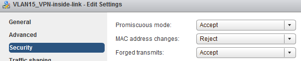
At some point of configuration (when adding the Router interface or so) the configuration GUI warns that promiscuous mode is needed in the virtual machine inside NIC. That is true because vSphere does not know about the MAC address that is assigned to the Virtual L3 Switch LAN hub interface (10.1.1.5). That is not the same as the MAC address of the VM’s NIC (with IP address 10.1.1.4). Therefore vSphere does not know where to forward the traffic.
Thus promiscuous mode needs to be enabled in the VPN-link port group in the vSphere virtual switch configurations. That enables the VM to receive all the necessary traffic.
Also the forged transmits setting needs to be enabled to make vSphere accept the packets sent by the virtual hub.
Finally
There it is, a VPN server that can be accessed with the usual Windows and Mac VPN clients.
This post is very easy to understand and implement softether VPN. If you can explain how to setup the Radius server that would be helpful.
Hi venky, sorry but I did not set up the RADIUS myself, I used an existing Microsoft-based server for this implementation.
Thanks Markku Leiniö for the reply, aim trying to setup RADIUS server on Debian OS.
This is a very well laid out and easy to follow doc (at least for anyone with routeing knowledge). I’m aware this is several years old but the concept never changes. Thank you Markku!
Thank you for this guide. I followed this and got stuck a this stack:
The internal NIC with address 10.1.1.4 and the virtual layer 3 switch interface with address 10.1.1.5 could not reach each other, that means no connectivity between VPN pool and internal network. Please suggest what should be done on the VPN server?
Hi, I don’t have this setup anymore, so I don’t have an exact answer to you. I’m not even sure if the two addresses should be able to reach each other, due to them existing in the same device in a bit strange way (the VM forwarding can present a situation here: Linux is maybe sending the packets to the switch but switch does not forward them back in the same port etc.). I would rather concentrate on checking that your all other configurations are correctly set for VPN pool forwarding to happen. Wireshark or tcpdump can be helpful when verifying if packets reach the correct destinations. I’m wondering if Linux IP forwarding was enabled in some phase of the installation (/etc/sysctl.conf: net.ipv4.ip_forward=1).