Other posts about EVPN/VXLAN in Proxmox VE:
- Configuring VXLAN in Proxmox VE (this post)
- Configuring EVPN for L2 VXLAN in Proxmox VE
- EVPN ARP/ND Suppression in Proxmox VE
About VXLAN
From Wikipedia:
Virtual eXtensible LAN (VXLAN) is a network virtualization technology that uses a VLAN-like encapsulation technique to encapsulate OSI layer 2 Ethernet frames within layer 4 UDP datagrams, using 4789 as the default IANA-assigned destination UDP port number, although many implementations that predate the IANA assignment use port 8472. VXLAN attempts to address the scalability problems associated with large cloud computing deployments. VXLAN endpoints, which terminate VXLAN tunnels and may be either virtual or physical switch ports, are known as VXLAN tunnel endpoints (VTEPs).
See also RFC 7348 (Virtual eXtensible Local Area Network (VXLAN): A Framework for Overlaying Virtualized Layer 2 Networks over Layer 3 Networks).
What it means in practice is that if we want to transmit this Ethernet frame using VXLAN encapsulation:
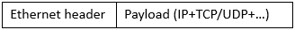
we will add some headers to the original frame and send it away:

To make it possible to transmit the usual max 1500-byte payload in the original frame, we need to increase the MTU (Maximum Transmission Unit) value to 1550 due to the extra headers:
- 14 bytes Ethernet
- 20 bytes IP (in this IPv4 example)
- 8 bytes UDP
- 8 bytes VXLAN
Those mean 50 bytes extra in total, thus MTU 1550 is the minimum when encapsulating with VXLAN.
Ok, that was a bit technical right from the start, but in practice this VXLAN stuff means that we can now transmit Ethernet frames over IP transport, even over routed networks.
VXLAN use case with Proxmox Virtual Environment
VXLAN as a network virtualization feature fits nicely in Proxmox Virtual Environment (PVE). Using VXLAN makes it possible to create layer 2 virtual networks without configuring them separately on the physical network. The virtual networks can be used for the virtual machines running on the PVE cluster.
Let’s imagine a simple example of two virtual machines running on different PVE nodes, and those two VMs need to communicate directly with each other with an isolated network.
In traditional networking we would create a new VLAN on the physical network switches, ensuring that we reconfigure the PVE-connected switch ports with the new VLAN, also adding the new VLAN in the PVE configurations. This would also require that the VLANs were extended to all PVE nodes regardless of their physical location.
Then imagine you have hundreds or thousands of VM applications that need the same kind of isolated networking: you’d need to configure all those VLANs in the switches, ports and PVE nodes per application. (Also remember that you cannot have more than 4094 VLANs in the same network without additional tricks.)
With VXLAN you only need to configure the physical network once to add a VXLAN underlay network for the PVE nodes, and then you can create all the required VXLAN overlay networks just on the PVE cluster.
Let’s see how it goes when configuring the simple example in practice: creating a VXLAN overlay network for the VMs.
Configuring VXLAN underlay
First we need to configure the underlay network, enabling the PVE nodes to send and receive the VXLAN packets between each other.
I have four PVE version 9.1 nodes in my PVE datacenter cluster. Initially all the nodes have very basic network setup:
- On each node there is a Linux bridge called
vmbr0 - One physical port on the PVE node (
enp4s0in the example below) is associated with thevmbr0bridge - MTU is set to 9000 on both
vmbr0and the physical port (as well as on the physical switches) to be able to use jumbo frames
- On that
vmbr0bridge on each host, there is a Linux VLAN interfacevmbr0.10(VLAN 10) that is used for the management connectivity of the PVE node - VLAN 10 is tagged on the physical switch port
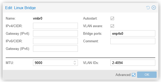
Now, for the VXLAN underlay connectivity between the nodes, I could use that vmbr0.10. But for clarity and traffic separation, I will create a new Linux VLAN interface for VXLAN underlay on each PVE node: vmbr0.31. (I could also use a separate physical port, but I didn’t do that here, I’ll just use the existing VLAN trunk port.) VLAN 31 is allocated the 192.168.15.0/24 network in this lab. MTU needs also be configured to be at least 1550 bytes, in order to support VXLAN tunneling of the usual max 1500-byte IP packets. This is how vmbr0.31 looks like now on the first PVE node (pve1):
Note that the 192.168.15.0/24 network is not routed anywhere, meaning that it is not reachable from other IP networks, so there is no gateway address configured. This network is only used between the PVE nodes, and all the nodes are on the same VLAN in this setup. Obviously, the physical network is also configured to carry VLAN 31 tagged on the switch port.
These vmbr0.31 interfaces on each PVE node are the VTEP interfaces.
At this point we should have connectivity between the VTEP interfaces, for example from pve2 to pve1:
root@pve2:~# ping 192.168.15.11
PING 192.168.15.11 (192.168.15.11) 56(84) bytes of data.
64 bytes from 192.168.15.11: icmp_seq=1 ttl=64 time=0.207 ms
64 bytes from 192.168.15.11: icmp_seq=2 ttl=64 time=0.260 ms
64 bytes from 192.168.15.11: icmp_seq=3 ttl=64 time=0.236 ms
^C
--- 192.168.15.11 ping statistics ---
3 packets transmitted, 3 received, 0% packet loss, time 2076ms
rtt min/avg/max/mdev = 0.207/0.234/0.260/0.021 ms
root@pve2:~#
Note that the ICMP packets above were sized only 84 bytes in total (20 bytes IPv4 + 8 bytes ICMP + 56 bytes ping payload), while in order to keep the usual 1500-byte MTU inside the VXLAN tunnel, we need to be able to transmit at least 1550-byte packets, so let’s test that as well (first with 1550 and then with 1551 bytes, setting the Don’t Fragment flag in the packets):
root@pve2:~# ping 192.168.15.11 -s 1522 -M do
PING 192.168.15.11 (192.168.15.11) 1522(1550) bytes of data.
1530 bytes from 192.168.15.11: icmp_seq=1 ttl=64 time=0.334 ms
1530 bytes from 192.168.15.11: icmp_seq=2 ttl=64 time=0.316 ms
1530 bytes from 192.168.15.11: icmp_seq=3 ttl=64 time=0.302 ms
^C
--- 192.168.15.11 ping statistics ---
3 packets transmitted, 3 received, 0% packet loss, time 2042ms
rtt min/avg/max/mdev = 0.302/0.317/0.334/0.013 ms
root@pve2:~# ping 192.168.15.11 -s 1523 -M do
PING 192.168.15.11 (192.168.15.11) 1523(1551) bytes of data.
ping: sendmsg: Message too long
ping: sendmsg: Message too long
ping: sendmsg: Message too long
^C
--- 192.168.15.11 ping statistics ---
3 packets transmitted, 0 received, +3 errors, 100% packet loss, time 2067ms

root@pve2:~#
This shows us successful communication with 1550-byte packets between the VTEP interfaces of the PVE nodes.
This is just normal IP connectivity between the PVE nodes, just ensuring that a bit larger packets also come through. There are no specific VXLAN feature requirements for the physical switches or routers to get VXLAN working between the PVE nodes.
Note that this is a simple example of an underlay network implementation where all PVE nodes are connected to the same VLAN and IP subnet. The underlay network could also be a routed network where all or some of the PVE nodes are in different subnets, like when the nodes are in different datacenters. For VXLAN it doesn’t matter as long as the VTEPs can reach each other in the underlay.
Configuring VXLAN overlay
Then comes the VXLAN overlay configuration. In PVE it is done in the SDN (Software-Defined Network) section on the datacenter level.
In the SDN – Zones section, I’ll add a new VXLAN zone:
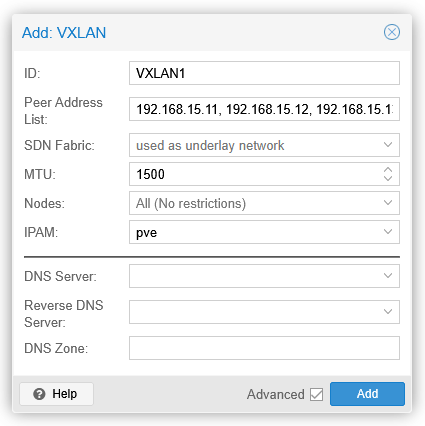
A VXLAN zone is a construct that will contain the VXLAN VNet I’ll create below. Peer Address List is the list of all PVE nodes in my lab, specifically the VTEP addresses. Alternatively an SDN fabric could be selected, but since I haven’t configured one yet, I’ll just list the VTEP IP addresses.
MTU is 1500, so that will be the largest packet size that will be supported on top of the VXLAN underlay.
After clicking Add the new zone will be shown with state of new. This means that the configuration has not yet been applied to the PVE nodes.
I’ll then create a new VNet in the SDN – VNets section:
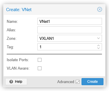
The VNet name is limited to 8 characters, but the alias field can be used for more descriptive name if needed. Zone is the VXLAN1 zone I created above, and the tag field is a 24-bit integer value from 1 to 16777215 (224-1). The tag value is the VXLAN Network Identifier (VNI) in the VXLAN header.
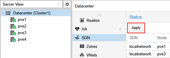
After creating VNet1 I’ll go to the top-level SDN section and click the Apply button there, to actually configure all the PVE nodes with the new VXLAN setup.
Additional VNets can be created later using the same VXLAN1 zone as needed. The VNets will be isolated from each other even though they will use the same VXLAN underlay network.
Using the VXLAN configuration for VMs
I have two VMs already running on different PVE nodes: testserver1 is on pve1 and testserver2 is on pve2. I’ll now add them the new dedicated VNet1 network by adding a new network interface on both VMs:
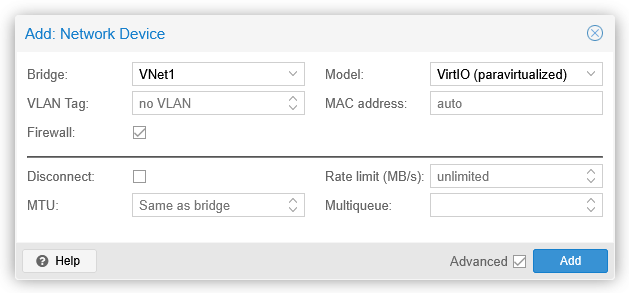
In the Bridge field I select VNet1, and click Add.
On both VMs I can immediately see a new ens19 interface (the actual interface name may vary):
markku@testserver1:~$ ip link show ens19
3: ens19: <BROADCAST,MULTICAST> mtu 1500 qdisc noop state DOWN mode DEFAULT group default qlen 1000
    link/ether bc:24:11:f3:ea:1c brd ff:ff:ff:ff:ff:ff
    altname enp0s19
markku@testserver1:~$

markku@testserver2:~$ ip link show ens19
3: ens19: <BROADCAST,MULTICAST> mtu 1500 qdisc noop state DOWN mode DEFAULT group default qlen 1000
    link/ether bc:24:11:b8:45:a3 brd ff:ff:ff:ff:ff:ff
    altname enp0s19
markku@testserver2:~$
MTU seems to be 1500 right away, we’ll verify that in a minute.
I’ll now configure the interface IP address on the VMs (this is just a temporary setup so a couple of ip commands work for now, no need to set them in the permanent configuration files):
sudo ip addr add 10.10.10.xx/24 dev ens19
sudo ip link set up ens19
Let’s try to ping testserver2 (10.10.10.12) from testserver1 (10.10.10.11):
markku@testserver1:~$ ping 10.10.10.12 -s 1472 -M do
PING 10.10.10.12 (10.10.10.12) 1472(1500) bytes of data.
1480 bytes from 10.10.10.12: icmp_seq=1 ttl=64 time=0.511 ms
1480 bytes from 10.10.10.12: icmp_seq=2 ttl=64 time=0.558 ms
1480 bytes from 10.10.10.12: icmp_seq=3 ttl=64 time=0.533 ms
^C
--- 10.10.10.12 ping statistics ---
3 packets transmitted, 3 received, 0% packet loss, time 2055ms
rtt min/avg/max/mdev = 0.511/0.534/0.558/0.019 ms
markku@testserver1:~$ ping 10.10.10.12 -s 1473 -M do
PING 10.10.10.12 (10.10.10.12) 1473(1501) bytes of data.
ping: local error: message too long, mtu=1500
ping: local error: message too long, mtu=1500
ping: local error: message too long, mtu=1500
^C
--- 10.10.10.12 ping statistics ---
3 packets transmitted, 0 received, +3 errors, 100% packet loss, time 2048ms

markku@testserver1:~$ ip neigh show dev ens19
10.10.10.12 lladdr bc:24:11:b8:45:a3 REACHABLE
markku@testserver1:~$
Looks good: MTU is 1500 bytes as promised, and the servers can reach each other over the new VXLAN overlay network.
VXLAN packets on the wire
Let’s also see how the VXLAN-encapsulated packets look like in Wireshark when captured in the actual physical network. I have configured port mirroring on one of the switches so that I can capture all traffic to and from pve1 on my remote sniffer host.
A max-sized (1500 bytes) ping packet from testserver1 (on pve1) to testserver2 (on pve2) (the dissection output has been manually edited for readability):
> Frame 54: Packet, 1568 bytes on wire (12544 bits), 1568 bytes captured (12544 bits) on interface sshdump, id 0
> Ethernet II,
  Src: MicroStarInt_40:44:19 (d4:3d:7e:40:44:19),
  Dst: LCFCElectron_d2:f0:49 (e8:6a:64:d2:f0:49)
> 802.1Q Virtual LAN, PRI: 0, DEI: 0, ID: 31
> Internet Protocol Version 4, Src: 192.168.15.11, Dst: 192.168.15.12
> User Datagram Protocol, Src Port: 43973, Dst Port: 4789
v Virtual eXtensible Local Area Network
      Flags: 0x0800, VXLAN Network ID (VNI)
          0... .... .... .... = GBP Extension: Not defined
          .... 1... .... .... = VXLAN Network ID (VNI): True
          .... .... .0.. .... = Don't Learn: False
          .... .... .... 0... = Policy Applied: False
          .000 .000 0.00 .000 = Reserved(R): 0x0000
      Group Policy ID: 0
      VXLAN Network Identifier (VNI): 1
      Reserved: 0
> Ethernet II,
  Src: ProxmoxServe_f3:ea:1c (bc:24:11:f3:ea:1c),
  Dst: ProxmoxServe_b8:45:a3 (bc:24:11:b8:45:a3)
> Internet Protocol Version 4, Src: 10.10.10.11, Dst: 10.10.10.12
> Internet Control Message Protocol
If we look this output from bottom to top, we first see the original ICMP packet, from 10.10.10.11 to 10.10.10.12, with the MAC addresses of testserver1 and testserver2 network interfaces. This is the inner packet that was sent by the VM.
Then there are the outer packet headers, added by the PVE node. First the VXLAN header, showing VNI 1, as configured in our VNet1 in the PVE SDN. Above it there is the UDP header, with a random source port (43973 in this case) and the well-known VXLAN port 4789 as the destination port, and then the other VXLAN underlay-related information: IP addresses of the VTEPs (192.168.15.11 for pve1 and 192.168.15.12 for pve2), VLAN 31 as configured in my lab, and the MAC addresses of the physical NICs of the PVE nodes.
This was a common example of a unicast packet between two hosts.
But what happens if there is a new VM connected to the same VNet1 virtual network on a different PVE node?
I added testserver3 (10.10.10.13) on pve3 to VNet1 and then pinged it from testserver1.
Now, at this point the source VM does not know the MAC address of 10.10.10.13, so it needs to broadcast an ARP request to find it out. In the VXLAN underlay it looked like this:
> Frame 136: Packet, 96 bytes on wire (768 bits), 96 bytes captured (768 bits) on interface sshdump, id 0
> Ethernet II,
  Src: MicroStarInt_40:44:19 (d4:3d:7e:40:44:19),
  Dst: LCFCElectron_f8:35:a2 (00:2b:67:f8:35:a2)
> 802.1Q Virtual LAN, PRI: 0, DEI: 0, ID: 31
> Internet Protocol Version 4, Src: 192.168.15.11, Dst: 192.168.15.14
> User Datagram Protocol, Src Port: 41220, Dst Port: 4789
> Virtual eXtensible Local Area Network
> Ethernet II,
  Src: ProxmoxServe_f3:ea:1c (bc:24:11:f3:ea:1c),
  Dst: Broadcast (ff:ff:ff:ff:ff:ff)
> Address Resolution Protocol (request)

> Frame 137: Packet, 96 bytes on wire (768 bits), 96 bytes captured (768 bits) on interface sshdump, id 0
> Ethernet II,
  Src: MicroStarInt_40:44:19 (d4:3d:7e:40:44:19),
  Dst: UniversalGlo_3a:d5:fd (44:39:c4:3a:d5:fd)
> 802.1Q Virtual LAN, PRI: 0, DEI: 0, ID: 31
> Internet Protocol Version 4, Src: 192.168.15.11, Dst: 192.168.15.13
> User Datagram Protocol, Src Port: 41220, Dst Port: 4789
> Virtual eXtensible Local Area Network
> Ethernet II,
  Src: ProxmoxServe_f3:ea:1c (bc:24:11:f3:ea:1c),
  Dst: Broadcast (ff:ff:ff:ff:ff:ff)
> Address Resolution Protocol (request)

> Frame 138: Packet, 96 bytes on wire (768 bits), 96 bytes captured (768 bits) on interface sshdump, id 0
> Ethernet II,
  Src: MicroStarInt_40:44:19 (d4:3d:7e:40:44:19),
  Dst: LCFCElectron_d2:f0:49 (e8:6a:64:d2:f0:49)
> 802.1Q Virtual LAN, PRI: 0, DEI: 0, ID: 31
> Internet Protocol Version 4, Src: 192.168.15.11, Dst: 192.168.15.12
> User Datagram Protocol, Src Port: 41220, Dst Port: 4789
> Virtual eXtensible Local Area Network
> Ethernet II,
  Src: ProxmoxServe_f3:ea:1c (bc:24:11:f3:ea:1c),
  Dst: Broadcast (ff:ff:ff:ff:ff:ff)
> Address Resolution Protocol (request)

> Frame 139: Packet, 96 bytes on wire (768 bits), 96 bytes captured (768 bits) on interface sshdump, id 0
> Ethernet II,
  Src: UniversalGlo_3a:d5:fd (44:39:c4:3a:d5:fd),
  Dst: MicroStarInt_40:44:19 (d4:3d:7e:40:44:19)
> 802.1Q Virtual LAN, PRI: 0, DEI: 0, ID: 31
> Internet Protocol Version 4, Src: 192.168.15.13, Dst: 192.168.15.11
> User Datagram Protocol, Src Port: 51922, Dst Port: 4789
> Virtual eXtensible Local Area Network
> Ethernet II,
  Src: ProxmoxServe_9d:fc:fc (bc:24:11:9d:fc:fc),
  Dst: ProxmoxServe_f3:ea:1c (bc:24:11:f3:ea:1c)
> Address Resolution Protocol (reply)
Since the original frame was destined to broadcast address, the source PVE node VXLAN-encapsulated and replicated the frame to all other VTEPs in the same VXLAN zone.
Testserver3 then got the ARP request and responded with ARP reply, and pve3 VXLAN-encapsulated it and sent to pve1 only (where the source VM is).
In VXLAN underlays multicast can also be used instead of replicating the broadcast and unknown unicast packets per VTEP, but I don’t see PVE SDN supporting it.
SDN fabric in PVE
In the VXLAN zone configuration above the VTEP addresses (PVE nodes) were manually listed to tell PVE SDN where all the VTEPs are.
Using SDN fabric in PVE removes the need to manually specify the VTEP addresses in VXLAN zones.
Let’s add a fabric with OSPF (Open Shortest Path First) in SDN – Fabrics in the PVE datacenter:
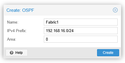
The IPv4 prefix is the address range for the allowed OSPF router IDs. OSPF sessions won’t be established if the OSPF router IDs don’t match this.
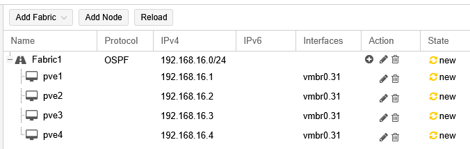
After creating the fabric, all the PVE nodes need to be added to the fabric by selecting the fabric and using the Add Node button. For each node, I’ll select the vmbr0.31 interface, and then enter a new loopback address in the IPv4 field. The address will be used as the VTEP address and also as the OSPF router ID. To match the prefix above in the fabric settings, I’ll use 192.168.16.x according to the PVE node:
The SDN configurations need to be applied now in the SDN section before being able to use the new Fabric1 fabric in the VXLAN zone.
Note: When adding the nodes in the fabric and selecting the vmbr0.31 interface, there is a warning on the vmbr0.31 interface saying “Interface already has an address configured in /etc/network/interfaces”. It seems this warning can be safely ignored in this case. I also tried removing the vmbr0.31 interface IP addresses in the node configurations and then adding the nodes with the 192.168.16.x loopback addresses as described above, but that resulted in non-working OSPF point-to-point configurations for this setup where the nodes are connected to a shared VLAN. This was tested with PVE version 9.1.6.
Then, back in the SDN – Zones section, I’ll edit the VXLAN1 zone by removing the peer addresses and selecting the SDN fabric:
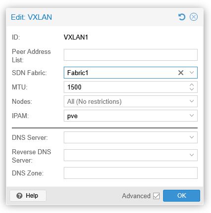
I’ll OK this and apply the SDN configuration once again.
Before testing the VXLAN encapsulation, let’s see the routing table on pve1:
root@pve1:~# ip route show dev vmbr0.31
192.168.15.0/24 proto kernel scope link src 192.168.15.11
192.168.16.2 nhid 47 via 192.168.15.12 proto ospf src 192.168.16.1 metric 20
192.168.16.3 nhid 49 via 192.168.15.13 proto ospf src 192.168.16.1 metric 20
192.168.16.4 nhid 45 via 192.168.15.14 proto ospf src 192.168.16.1 metric 20
root@pve1:~#
pve1 has successfully learned the 192.168.16.x VTEP addresses of the other nodes in the same VXLAN underlay network using the OSPF protocol. Similar effect can be observed on the other nodes as well.
Finally, let’s test the VXLAN overlay connectivity from testserver1 to testserver3:
markku@testserver1:~$ ping 10.10.10.13 -s 1472 -M do
PING 10.10.10.13 (10.10.10.13) 1472(1500) bytes of data.
1480 bytes from 10.10.10.13: icmp_seq=1 ttl=64 time=0.728 ms
1480 bytes from 10.10.10.13: icmp_seq=2 ttl=64 time=0.692 ms
1480 bytes from 10.10.10.13: icmp_seq=3 ttl=64 time=0.644 ms
^C
--- 10.10.10.13 ping statistics ---
3 packets transmitted, 3 received, 0% packet loss, time 2054ms
rtt min/avg/max/mdev = 0.644/0.688/0.728/0.034 ms
markku@testserver1:~$
There is no difference in the actual VXLAN encapsulation when using the SDN fabric instead of specifying the VTEP addresses manually in the VXLAN zone.
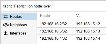
If you are interested in the protocol internals of the PVE SDN fabric, use the vtysh command to open the FRRouting shell on the PVE nodes, and then use commands like show running-config and show ip ospf neighbor to see how OSPF is configured and running on the nodes. In the PVE GUI you can see the routes and neighbors when browsing to Fabric1 under each PVE node:
Closing words
As shown, it is quite straightforward to set up VXLAN networking in Proxmox VE. After the one-time VXLAN underlay configuration you can create VXLAN VNets (overlay networks) for the virtual machine networking in the SDN section of the PVE datacenter.
Note that in the PVE SDN documentation it is currently mentioned that while the core SDN features are fully supported, the more advanced features like the SDN fabrics based on FRRouting are still in tech preview.